
Bench wiring guide
Porsche SDI6 bench pinout
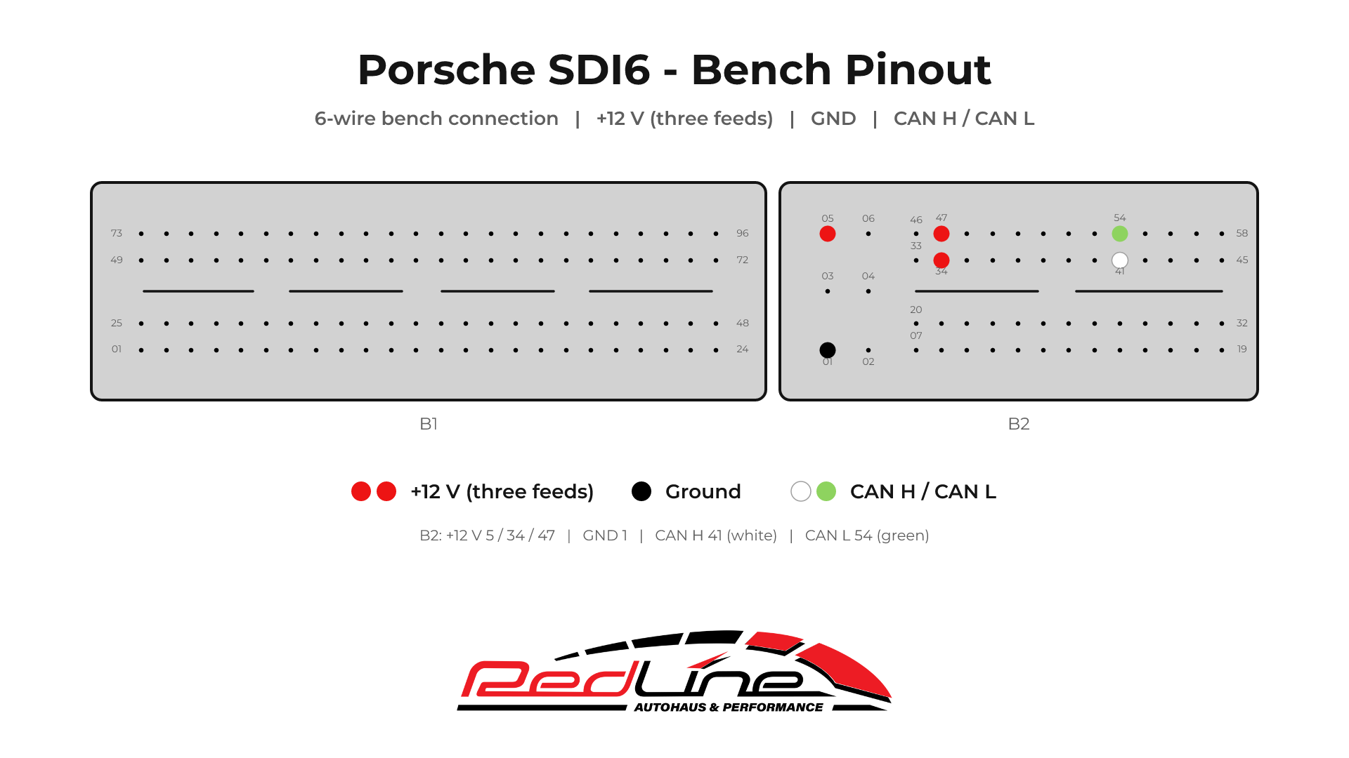
Connect the Porsche SDI6 ECU on the bench using its external connectors. This six-wire layout uses three power feeds, ground and CAN High / Low, with all connections on B2.
- Porsche
- SDI6
- Bench · ECU stays closed
- CAN · 500 kbit/s
1. Match the connectors
Look directly into the ECU connector face, as shown below: B1 is the larger 96-position connector on the left; B2 is the 58-position connector on the right. Use the moulded pin numbers to confirm orientation. The mating harness view is mirrored.
2. Wire connector B2
Turn the bench supply off before attaching the leads. The colours below follow the Redline diagrams; identify each lead by its signal if your harness uses different colours.
| Signal | B2 pin | Diagram colour | Connection |
|---|---|---|---|
| +12 V power | 5, 34 and 47 | Red | Connect all three power feeds. |
| Ground (GND) | 1 | Black | Common ground for the ECU, supply and interface. |
| CAN High (CAN H) | 41 | White | Connect to CAN H on your bench harness. |
| CAN Low (CAN L) | 54 | Green | Connect to CAN L on your bench harness. |
White stays CAN High; green stays CAN Low. Keep the CAN pair together and confirm both connections before powering the ECU.
3. Connect with Redline ECU Suite
- Confirm the ECU label identifies SDI6 and the connector layout matches this guide.
- With the supply off, connect the B2 ground, all three +12 V feeds and the CAN pair shown above. Use a regulated bench supply and the matching interface harness.
- Connect your supported J2534 interface to your computer. Open Redline ECU Suite, sign in and select your interface and the Porsche SDI6 protocol.
- Follow Suite's power-on prompts. The SDI6 protocol configures CAN at 500 kbit/s. This bench connection does not require opening the ECU or attaching a boot-pin lead.
- Identify the ECU, then run the available read operation and save the original file. Keep power and the interface connected until the operation finishes.
- End the session and switch off the bench supply before removing the wiring.
Check the live Porsche protocol listing for the available memory areas and read/write operations for your ECU. Match the ECU and software identification before selecting an operation.