
Bench wiring and boot reference
Hyundai / Kia SIM2K-241 pinout
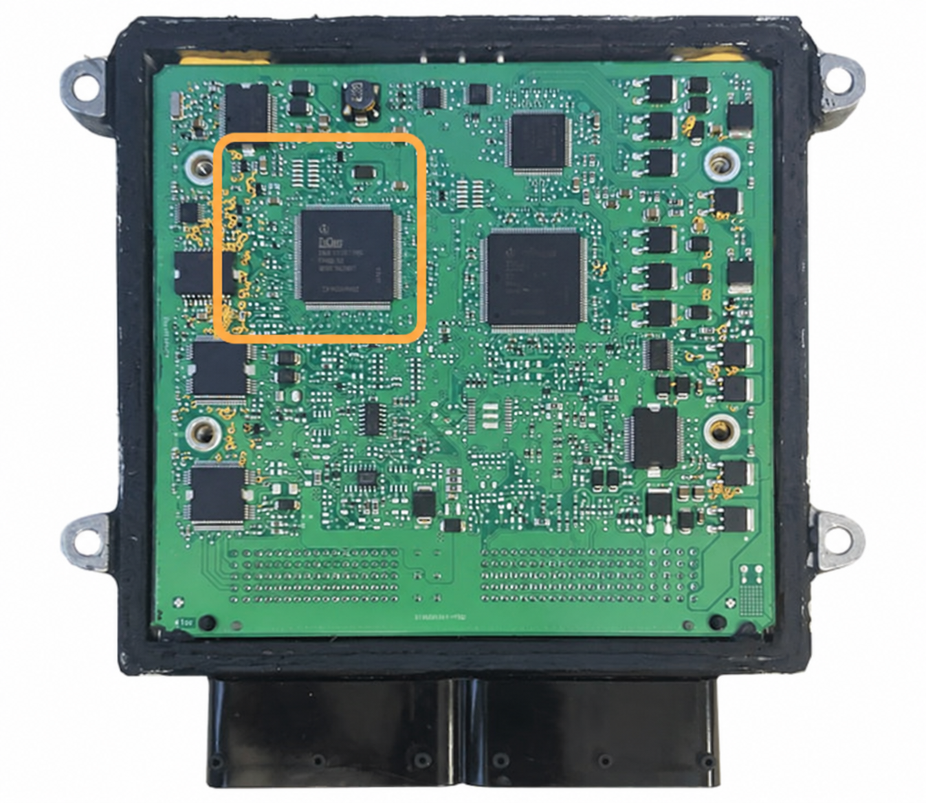
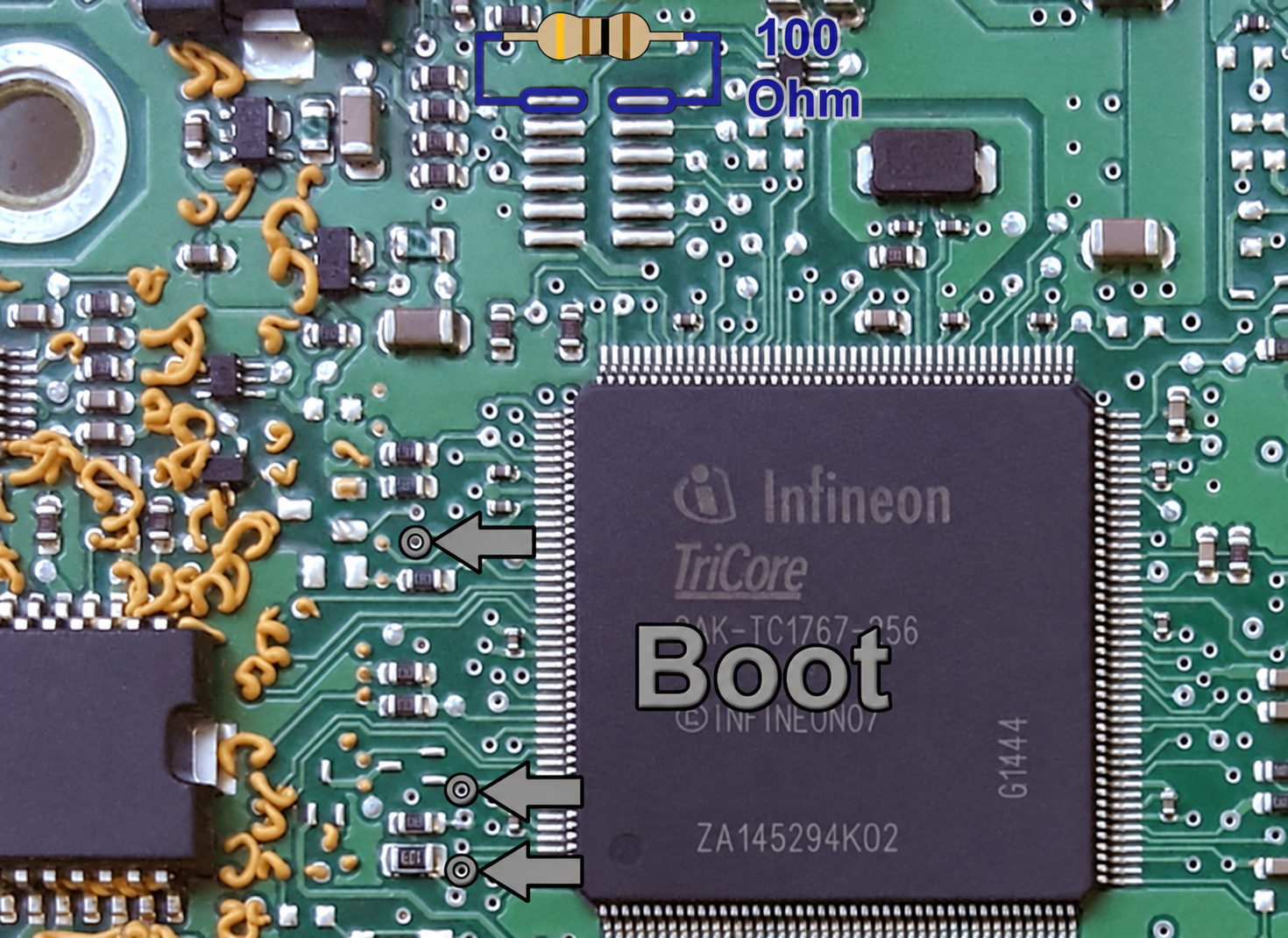
Two connector layouts for the Continental SIM2K-241 ECU. Match your connector housing and circuit board to the same option below, then use its connector diagram and boot images together.
- Hyundai
- Kia
- SIM2K-241
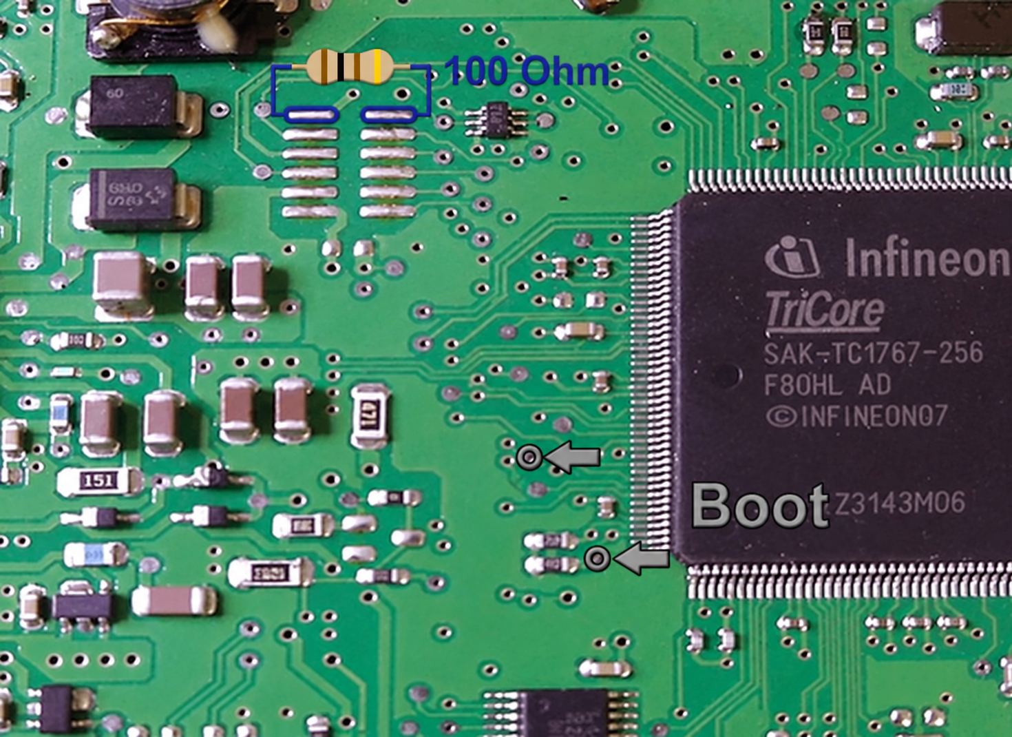
- Boot access · ECU opened
Red marks the power feeds, black marks ground, and white/green mark the main CAN pair. Match CAN H/L to your tool's harness. These are boot-mode bench references; access to the marked points requires opening the ECU.
Option 1
B1: 60 positions · B2: 94 positions
Connector pinout
B1 is on the left and B2 is on the right. The marked connections are on B2.
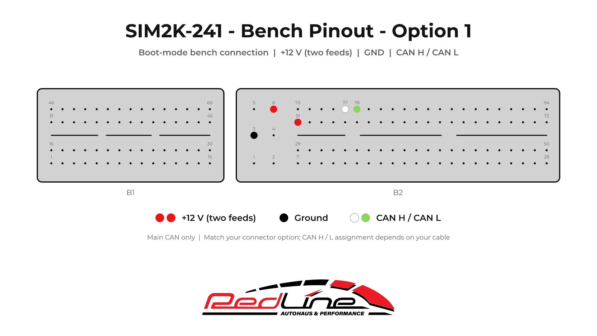
- Power · red
- B2 · 6 and 51
- Ground · black
- B2 · 3
- Main CAN pair · white/green
- B2 · 77 and 78
Board overview
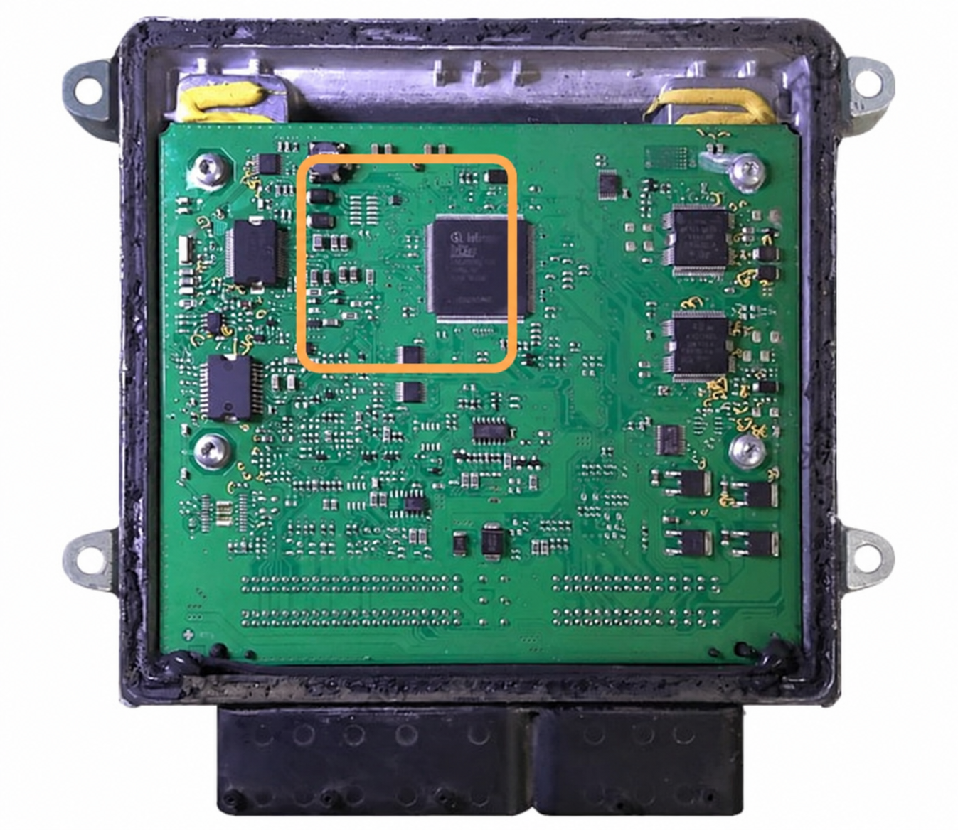
Boot-pin close-up
Option 2
B1: 105 positions · B2: 91 positions
Connector pinout
B1 is on the left and B2 is on the right. The marked connections are on B2. This diagram uses the main CAN channel only; CAN2 connections are omitted.
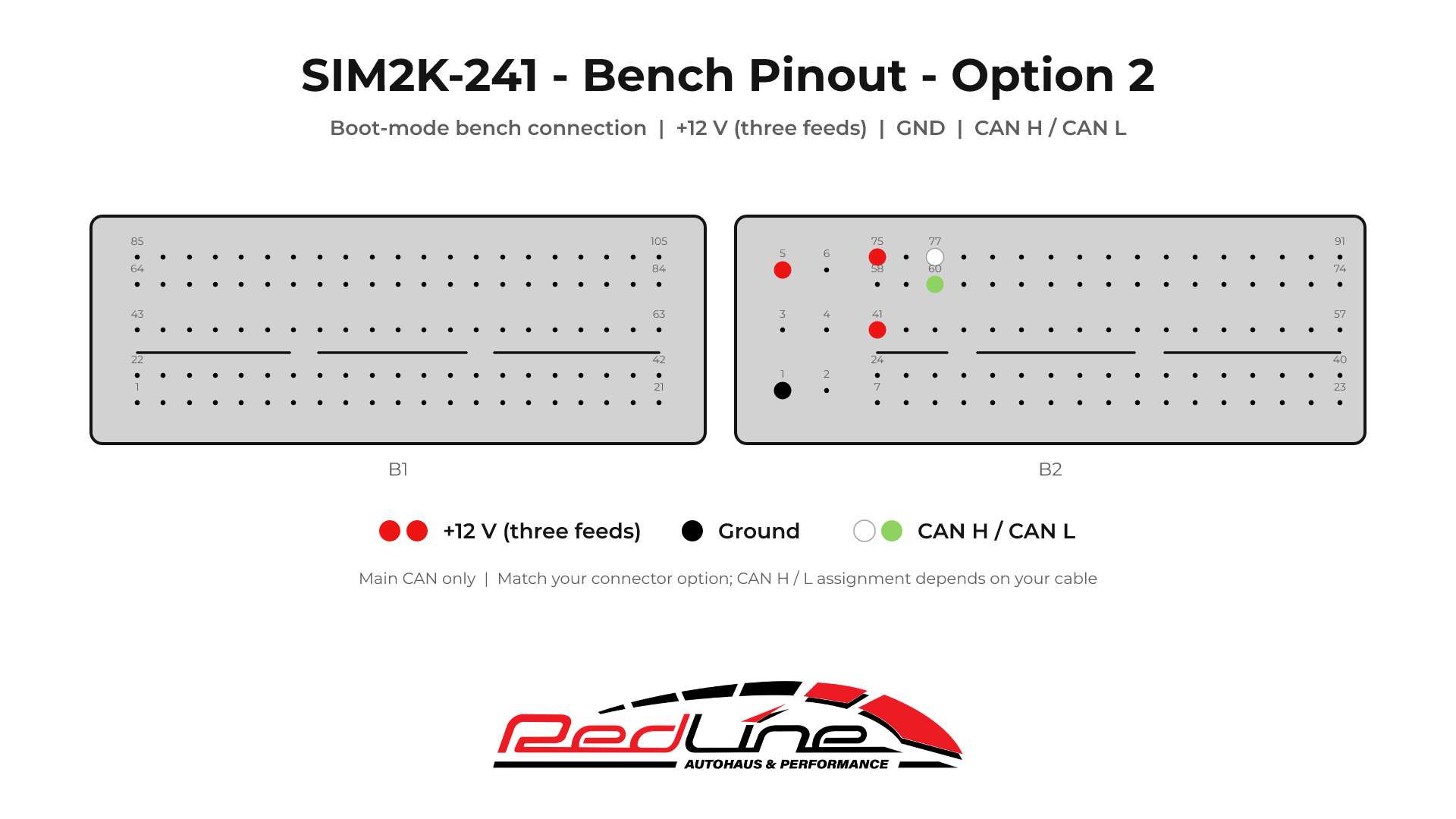
- Power · red
- B2 · 5, 41 and 75
- Ground · black
- B2 · 1
- Main CAN pair · white/green
- B2 · 77 and 60
Board overview
Boot-pin close-up
Hyundai and Kia coverage
This guide covers the two illustrated Continental SIM2K-241 layouts used by Hyundai and Kia. Confirm the ECU label, connector layout and circuit board together. The diagrams document connections; available read and write operations depend on the selected tool and protocol.